How to measure Current, Voltage and Resistance using a Processmeter/Multimeter
Processmeter/Multimeter?
A Multimeter/Processmeter, also known as a volt-ohm meter, is a handheld tester used to measure electrical voltage, current (amperage), resistance, and other values. Multimeters come in analog and digital versions and are useful for everything from simple tests, like measuring battery voltage, to detecting faults and complex diagnostics. They are one of the tools preferred by electricians for troubleshooting electrical problems on PLC's, motors, power supplies, circuits, and wiring systems. Technicians and Engineers MUST learn to use Multimeters for basic and complex measurements for troubleshooting's and control panel projects.
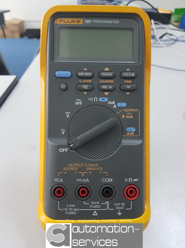
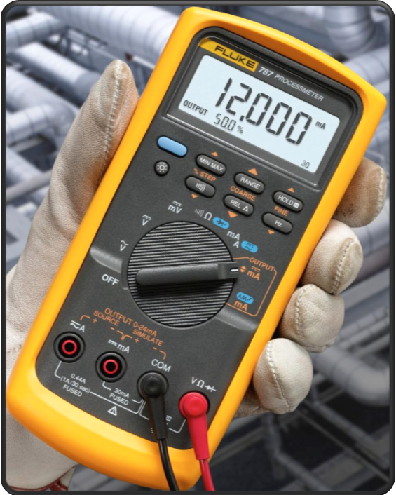
FLUKE 787 Processmeter
If you have any inquiry, just whatsapp ( Mr.TSoon) : +60163329691. If you think this site helpful, please share it on Facebook, Twitter, Linkedin or other social media using the share button above. thank you so much!
What Does a Multimeter/Processmeter Measure?
A basic Multimeter/Processmeter facilitates the activity of the subsequent quantities:
AC voltage.
AC (not all basic meters have this function).
DC voltage.
DC.
Continuity - indicated by a buzzer or tone.
Resistance.
Besides, meters could have subsequent functions:
Semiconductor HFE or DC gain.
Capacitance measurement.
Diode test.
Temperature with a further probe.
Inject Signals.
Frequency.
The worth calculable by the instrument is shown on a Digital showcase or scale. the center seat now and then has seven fragments of showcases.
What Does Volts, Ohms, Amps, Voltage Source, Load, Ground, AC, DC, Polarity Means?
Volts: A "volt" is a unit of electric potential, also known as electromotive force, and represents "the potential difference between two points of a conducting wire carrying a constant current of 1 ampere, when the power dissipated between these points is equal to 1 watt.
Ohms: "Ohm" is a unit of an electric circuit that is defined as the electrical resistance between two points of a conductor when a constant potential difference of one volt, applied to these points, produces in the conductor a current of one ampere, the conductor not being the seat of any electromotive force.
Amps: An "amp", short for ampere, is a unit of electrical current which SI defines in terms of other base units by measuring the electromagnetic force between electrical conductors carrying electric current.
Load: A gadget or component which pulls in control from a voltage supply. this may be Associate in Nursing electronic obstruction, bulb, space warmer, engine or any electrical machine.
Voltage Source: This delivers a present stream in a circuit. It could be a battery, compact generator, mains supply to a home, alternator on your motor or seat power supply in a lab or workshop
Ground: This is sometimes the purpose in a very circuit to that the negative terminal of battery or power provide is connected.
AC: Alternating Current. Current flows a technique from a supply, reverses, and so flows the opposite manner. This happens again and again a second at a rate determined by the frequency that is often fifty or sixty hertz. The mains offer in a very house is AC
DC: Direct current. Current streams only one technique from a DC supply, Associate in Nursing case of that might be a battery.
Polarity: A term acclimated portray the course of stream of current in an exceedingly circuit or that focuses square measure positive and that square measure negative wrt a point of reference.
How Do I check Volts, Ohms or Amps using a Multimeter/Processmeter
Voltage, current, and resistance range zone unit here and there set by turning a rotary choice dial. This is regularly set to the number being estimated, for example, PLC Power supply volts, DC volts, Amps(current) or Ohms (opposition).
Ranges in Voltage, Current and Resistance.
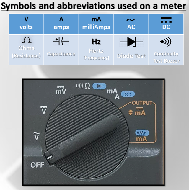
Range selector flip is used to select the symbols (volts, amps, resistance) and vary. See closely the symbols used for AC and DC.
WARNING !!! Damaged probes and check leads square measure a hazard. ne'er use a broken probe to live mains voltages!
Damaged wiring must be check before testing
How to Measure Current.
Turn off the power in the circuit being measured.
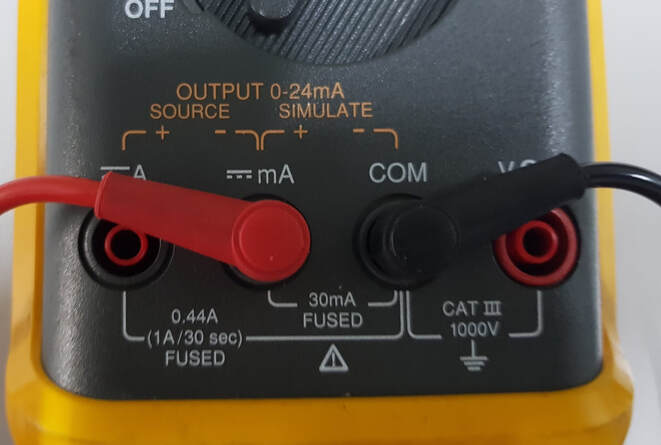
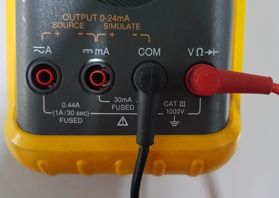
Connect the probe leads as shown in the photo below. Fitting the dark ground test lead into the COM attachment.
Plug the red positive probe lead either into the mA socket or the high current socket which is marked A (some meters have a 10 A socket instead of 0.44 A). The mA socket is often marked with the maximum current and if you estimate that the current will be greater than this value, you must use the 0.44 mA socket, else you will wind up blowing a fuse in the meter.
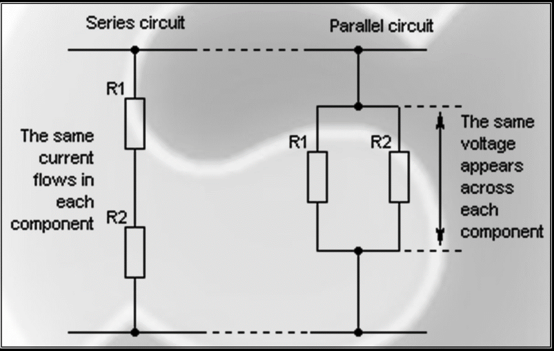
In order to measure current, multimeter must be inserted in series in a circuit. See the diagram below.
Turn the dial on the meter to the highest current range (or the 0.44 A range if the probe is in the 0.44 A socket). If the meter is autoranging, set it to the "A" or mA setting. (See the photo above for an explanation of symbols used).
Turn on the power.
If the range is too high, you can switch to a lower range to get a more accurate reading.
After finish measuring current , make sure you REMEMBER to return the positive probe back to the V socket. The meter is practically a short circuit when the lead is in the mA or 0.44 A socket. You may end up BLOWING the fuse or maybe BLOWING the meter at WORST! if you forget and connect the meter to a voltage source when the lead is in this position.(On some meters the 10A range is un-fused).
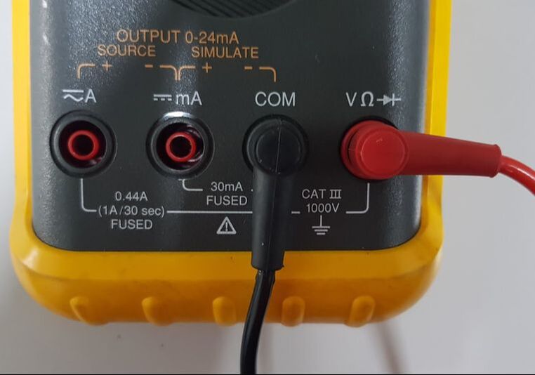
Measure Current by Connecting Probe Leads.
Test leads and sockets on a DPM, setup to measure current
Meter in Series for Measuring Current
To measure current flowing through it, DMM connected in series with load.
Step by step instructions to Measure Voltage.
Turn off the strands / cable tested if there is risk of shorting out the neighboring cables firmly divided, terminal or a different focus that has a wide range of voltages.
Attach ground black test lead to COM attachment on the meter.
red slots positive test leads to attachment labeled as V (usually added separately with the Greek symbol "omega" Ω and symbols may diodes).
possible chance that the meter has a variety of call setup wizard, select AC or DC volts and select the range to provide the required precision. So for example, estimates that 14 volts at 24 volts will give more decimal places than at 750 volts extend. In the event that the meter autoranging, turn the dial to the 'V' arrangement with pictures for AC or DC (see "What Symbols on Dial Range Mean?" Below).
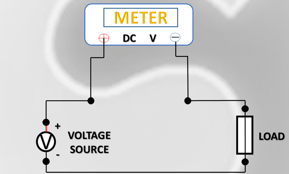
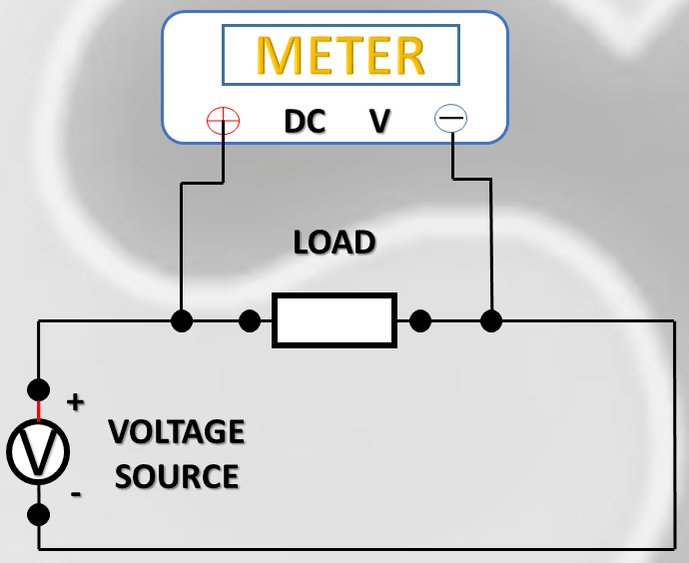
A multi-meter must be linked in parallel in the circuit (see figure below) so as to measure the voltage. So this means the two test probes to be linked in parallel with a voltage source, load or some two other points where the transverse voltage has to be estimated.
Black Pin Electronics Test Lead on the main points of the network / cable.
Turn on the power.
Touch the red end of the other of the second point of the circuit / wiring. Guarantee you do not cross the barrier between the reality of things to try and adjacent cables, terminal or tracks on the PCB.
Reading is displayed on the LCD screen.
Note: A lead with a 4mm banana plug toward one aspect and a crocodilian cut on the alternative finish is useful. The croc clasp will be related to the bottom within the circuit, gap up one in every of your hands.
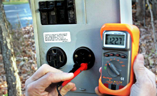
Measure Voltage by Connecting Probe Leads.
Test leads and 4mm sockets on a Processmeter, slot in to measure voltage
Series and Parallel Connections.
Image showing series and parallel circuit connections (R1 and R2 are resistors)
Meter in Parallel With Load for Measuring Voltage.
To measure voltage across it, DMM connected in parallel with load
WARNING By measuring voltages, always turn off the power before connecting measuring probes. Always connect to the first neutral.
WARNING !!! When Measuring Mains Voltages, SAFETY FIRST!!!
Before using a meter to measure voltage, ensure the test leads is not damaged and there are no exposed conductors which could be touched inadvertently.
Check that the test leads are mounted to a common socket and voltage DMM (see photo below) and is not a socket at this time. It is important to avoid reprimand meters.
Set the dial on the meter's varied volt AC and high voltage also varies.
Always turn off (if possible) before inserting the probe into the socket outlet, using the switch on the socket. Insert the probe into the neutral pin first before inserting the probe into the hot (live) pin of the socket. "If you put a probe into the new (life) initial pin and broken meter, this may be flowing through the meter to probe neutral. If you then inadvertently touch the probe, there is the possibility of shock.
Finally, activating switches and the ability to live voltage.
Identifying Hot Wires that is LIVE!
A non-contact voltage detector Fluke is a standard tool in any tool kit electricians, but useful for homeowners as well. I use one of these for recognizing that the driver is live at any point I'm making no maintenance at home. Unlike a screwdriver neon tester (voltage tester), you can use one of these situations in living / cable parts are wrapped or covered with insulation and can not contact cables. It also comes in useful to check for a break in a power flex and where the rupture occurs.
Note: It's consider a smart thought to utilize a neon analyzer to twofold watch that power is unquestionably off when doing any electrical support.
The definition for Symbols on the Range Dial Mean?
Symbols used in an Automatic range DPM
What Processmeter Should I Buy for Industrial purpose?
Fluke, is the leading manufacturer of digital instrumentation, for PLC and Automation Projects or test, Fluke 787 Processmeter model is recommended for advance purpose use in control panel projects or for Automation Machines. This is a suitable meter and can measure AC and DC volts, resistance, check continuity, diodes, plus current output capability. Based on the trusted Fluke 87 DMM, the 787 adds the ability to measure, source, and simulate dc loop current with 1 microamp resolution and 0.05% accuracy. It puts a complete solution for troubleshooting and calibrating current loop applications in the palm of your hand so you can get more information, faster and easier. Link : https://www.fluke.com/en-us/product/calibration-tools/ma-loop-calibrators/fluke-787
Other option is the Fluke 789 which has a built-in 24 V loop supply which decrease the need for taking a separate power supply when doing offline transmitter testing. The IR communication port of the Fluke 789 allows data to be logged to optional Fluke View Software for graphical analysis and reporting. It will be slightly expensive compare to 787.
Autoranging Meters.
Autoranging is a great advantage to have on a digital multimeter. Autoranging saves you the hassle of having to know which range of value the resistance, capacitance, voltage or whatever electrical characteristic you’re finding falls under. The multimeter finds the value for you. With a manual ranging multimeter (no autoranging), there are preset ranges, and you have to know which range of value your component falls under to get the value reading.
Fluke 787 PROCESSMETER. This autoranging multimeter from Fluke, a leading manufacturer of electronic test equipment, has an accuracy of 0.05% on DC ranges. It has CAT III protection to 1000 volts
Step-by-Step to Measure Resistance.
Turn off the power if the component is on a circuit board or Machines.
Disconnect one end of the component if it's in a circuit. This may involve pulling off spade leads or desoldering. This is important as there may be other resistors or other components having resistance, in parallel with the component being measured.
Connect the probes as shown in the photo below.
For Ohm or Ω range, turn on the dial to the lowest. It might be 200 ohm range or something else same.
Before measured, place the probe tip at each end of the component.
If the display indicates "I", this means that resistance is greater than can be displayed on the configuration selected range, so you must turn the dial to the next higher rank. Repeat this until a value on the LCD display.
Measure Resistance Connecting Probe Leads.
To measure resistance, this is how a lead setup will look like
Check resistance on switch contacts
Step-by-Step to test Continuity and Fuses.
A multimeter is helpful for checking breaks in flexes of appliances, blown filaments in bulbs and blown fuses, and tracing paths/tracks on PCBs.
Flip the choosing dial on the meter to the continuity vary. This can be often indicated by a logo that sounds like a series of arcs of a circle (See the pic showing symbols used on meters above).
Connect the probe results in the meter as shown within the pic below.
If a conductor on a circuit board/ a wire in AN appliance has to be checked, make certain the device is battery-powered down.
Place the tip of a research at every finish of the conductor or fuse that has to be checked.
If resistance is a smaller amount than regarding thirty ohms, the meter can indicate this by by a beep tone or noisy sound.
The resistance is sometimes indicated on the show conjointly.
If there's break in continuity within the device being tested, AN overload indication, typically the digit "1", are displayed on the meter.
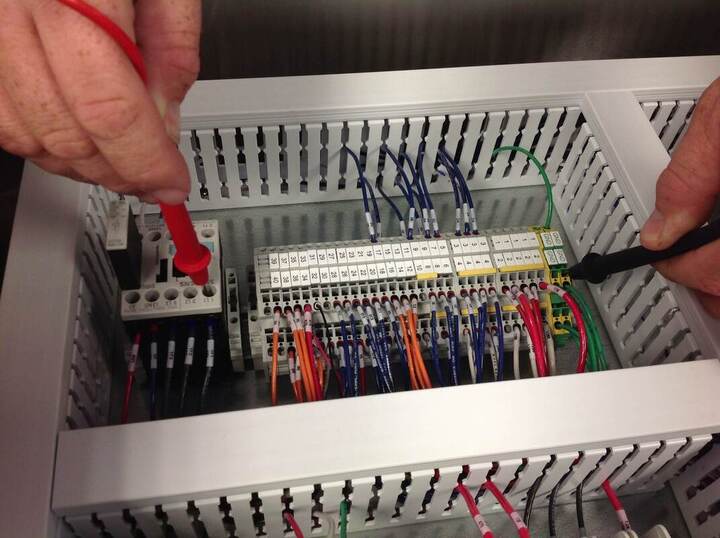
Multimeter/Processmeter point-to-point continuity check in PLC Control Panel
Test Diodes or Continuity by connecting the Probe Leads.
To check diodes or continuity, this is the Leads setup
Step-by-Step to test Diodes.
A multimeter can be utilized to check whether a diode is shortcircuited or open circuited. A diode is an electronic one way valve or check valve, which just leads a single way. A multimeter when associated with a working diode demonstrates the voltage over the segment.
Turn the dial of the meter to the diode test setting, which is indicated by a triangle with a bar at the end (see the photo showing symbols used on meters above).
Connect the probes as shown above.
Touch the tip of the negative probe to one end of the diode, and the tip of the positive probe to the other end.
When the black probe is in contact with the cathode of the diode (usually indicated by a bar marked on the component) and the red probe makes contact with the anode, the diode conducts, and the meter indicates the voltage. This should be about 0.2 volts for a Schottky diode and 0.6 volts for a silicon diode. When the probes are reversed, the meter should indicate a "1" because the diode is open circuit and non-conducting.
If the meter reads "1" when the probes are placed either way, the diode is likely to be faulty and open circuit. The Diode is shorted circuited if the meter indicates a value close to 0
If a component is in circuit, resistances in parallel will affect the reading and the meter may not indicate "1" but a value somewhat less.
How to use Multimeter/Processmeter to measure Wattage and Power consumption of an electronic board.
Watts = Volts x Current
Pros of Multimeter/Processmeters in PLC Projects.
Continuity checks for open wires. This take a look at is finished with a load.
Short Circuit checks for a minimum resistance between 2 wires - several megohms, often higher than what a multimeter can do.
Return of that investment is a long-term one and it will also save time.
Tests can be done 24/7.
Fewer human resources are required.
Reliability: It is more reliable and quicker way when running boring repetitive standardized tests which cannot be skipped.
It not only checks for continuity but also for shorts.
To test an input, connect a sensor and check for the light on the PLC/hook up a laptop and read the bit.
If you're testing an output, you'll want to use any regular multimeter from that output to the common. Make sure your reference line on the PLC output bank is what you intend. Most will make a connection from that to your output, so both should be "positive".
This is assuming you're not trying to read some complicated measurement like if an output is pulsing the right number of times per second.
If you are looking to speculate in your method management future, a Fluke 787 method Meter is comparatively dear, however it's capable of everything you'll want in your method management future. you'll be able to source/simulate analog signals yet as typical multi meter function/troubleshooting use cases. more down the road, for simple troubleshooting, inspect a Fluke 771 milliamp clamp meter, has virtually saved Pine Tree State days of labor put together.
Multimeters/Processmeters FAQ's
How Do You Check Voltage With a Multimeter/Processmeter? Slot the black color pin into COM socket and therefore the red pin into the socket marked "VΩ". Set the configuration to DC or AC volts and bit the pin tips to the 2 points between the voltage has to be calculated.
How Do You Check if a Wire is Live With a Multimeter? It is best to maintain security and use a volt meter contactless or phase tester screwdriver. These will indicate whether the voltage is for example> 100 volts. A multimeter can only measure the voltage between phase and neutral or live and ground if these conductors / terminals are available, which may not generally be the situation.
How Do You Check Voltage Drop With a Multimeter? Voltage drop happens over an opposition or along a power link. So pursue a similar method with respect to estimating voltage and measure voltage at the two points of interset and subtract one structure the other to gauge voltage drop.
Why is Voltage Drop Important? Link ought to be estimated sufficiently to limit voltage drop for the present it needs to convey and the separation over which current ventures.
In AS Automation Services , we provide detailed manual, fully equipped with PLC, HMI & SCADA hardware, software & laptop for cheapest price possible and we also provide one-to-one training in Malaysia For more info contact Mr.TSoon or Whatsapp @ +60163329691